QuickStart
This walkthrough uses a Teensy 4.1, but it works similarly with other compatible boards.
Upload a Sketch from the Arduino IDE
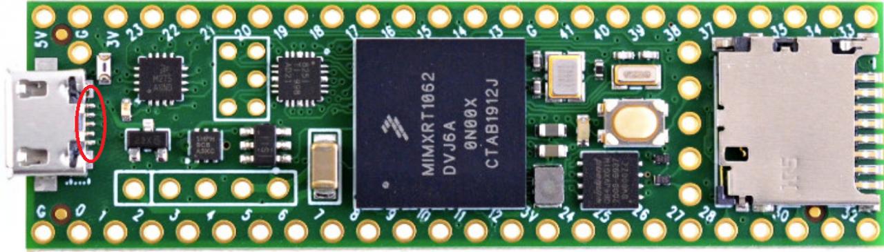
- Connect your Teensy board to the PC with a USB cable.
-
In the Arduino IDE, open
File > Examples > ViewPoint > Cartesian > HelloPlotter.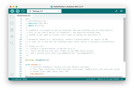
Read through the example comments if you want to understand the test behavior before uploading.
HelloPlotter is the “Hello, world!” of VoidLoop ViewPoint™
HelloPlotteris our recommended first test. The sketch uses the VoidLoop ViewPoint™ default configuration and streams one live trace labeledA0. -
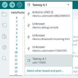
Choose your exact Teensy board model using the top dropdown, then select the Teensy USB serial port from the board and port selector.
-
Click Upload
 and wait for the compile and upload process to finish.
The sketch contains additional details on use with other MCUs (e.g., Arduino and ESP32).
Open VoidLoop ViewPoint™ and Connect to the Teensy
- Close the Arduino Serial Monitor and Serial Plotter if either is open.
- Open VoidLoop ViewPoint™.
- Open the Settings panel by clicking the gear icon
 in the top left.
 -
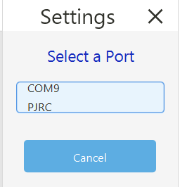
In the Serial Port section, click the port button (the top button) and choose the Teensy device. The correct port will clearly say “PJRC: Teensy” or “Teensyduino: Teensy”.
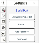
Select the Teensy device from the port list, then close the panel.
-
Click Connect
 .
.
Note
Because the Teensy 4.1 runs emulated serial over USB, specific serial parameters are unused.
The Connect/Disconnect icon looks like a plug: a red ✕ means no active connection, while a green checkmark means an active connection. The Play/Pause button stops and starts streaming without disconnecting from the serial port.
| Disconnected | Connected |
|---|---|
Confirm the First Live Plot
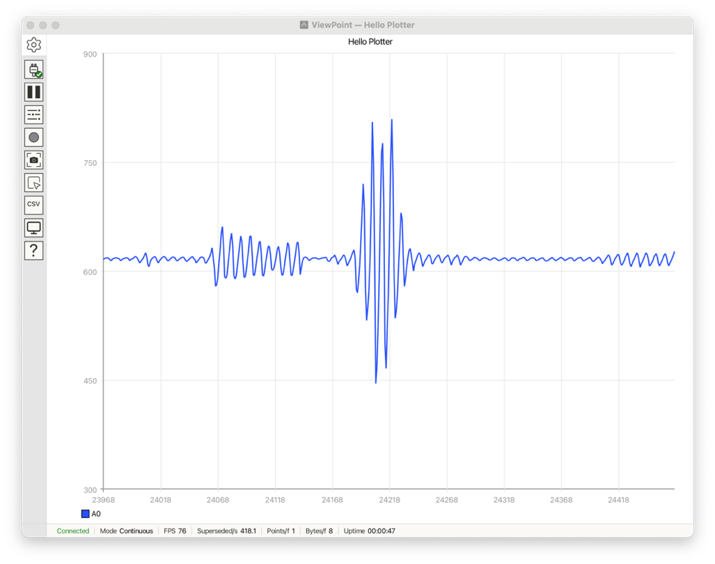
If nothing is connected to A0, the signal will usually show floating analog
noise. That is still a valid first-pass test, because it confirms that data is
being streamed from the Teensy into VoidLoop ViewPoint™.
For a more obvious changing signal, see
Signal Input Requirements first, then connect a signal
generator, potentiometer, or sensor to A0 and watch the plot update in real
time. Once you've added the “ADC” library to your Arduino libraries folder,
SignalAnalyzer_A0 is a more robust live-signal example that offers 800 kSPS
and 400 kHz bandwidth in both the time and frequency domains.
Mind your input levels
Depending on your MCU, use 3.0 Vpp with a 1.65 V offset and 50 Ω termination. See Signal Input Requirements before connecting a function generator.